Demo (0:14)
Kinetic Lamp
Brightening a meeting room with a kinetic display of art and engineering
JUN - JUL 2023 // WORK
When my office moved to a new building, our design coordinator challenged me to create a lighting showpiece for a blank-canvas meeting room. She wanted the piece to embody the idea of "radical creativity"—a catchphrase at Aalto University for the creative combination of art, engineering, and business. Taking inspiration from our university's name, which means "wave" in Finnish, I decided to design something that had movement and energy, much like our dynamic learning environment.
There were some unique constraints on the project: nothing could be mounted to the ceiling, and any electrical fixtures had to be plug-and-play (no wiring to the building power). So I had to invent some workarounds: I designed a wall-mounted lamp, controlled on a separate circuit by a standard plug-in lightbulb and a light-detecting resistor (LDR). That way, rather than adding a separate button to initiate the lamp's movement, I could ensure that the user experience in turning the room light on was as simple as can be. No switches had to be moved, and no structures of the room altered either.
DESIGN PROCESS
PROTOTYPING — ROUND 1
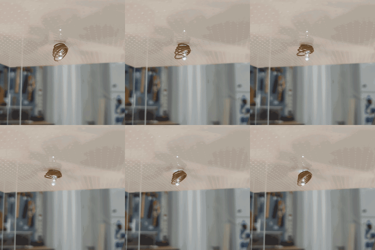
I first made a series of miniature prototypes from laser-cut wood, 3D-printed PLA, sheet metal, and LEDs. I wanted to experiment with various methods of movement—spinning, falling, climbing—but without wasting too much material.
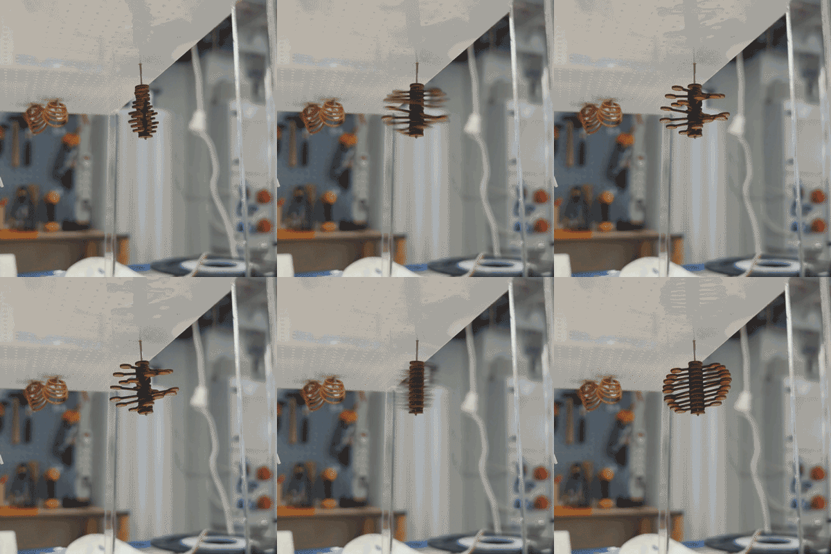
Our design coordinator chose her favorite: a flower-like design that dropped down to reveal an additional layer of shorter petals.
All of the early prototypes together—the chosen design is the white, finned object in the center
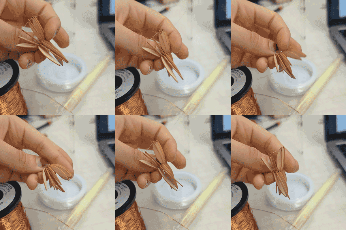
Inserting spacers between the "fins"
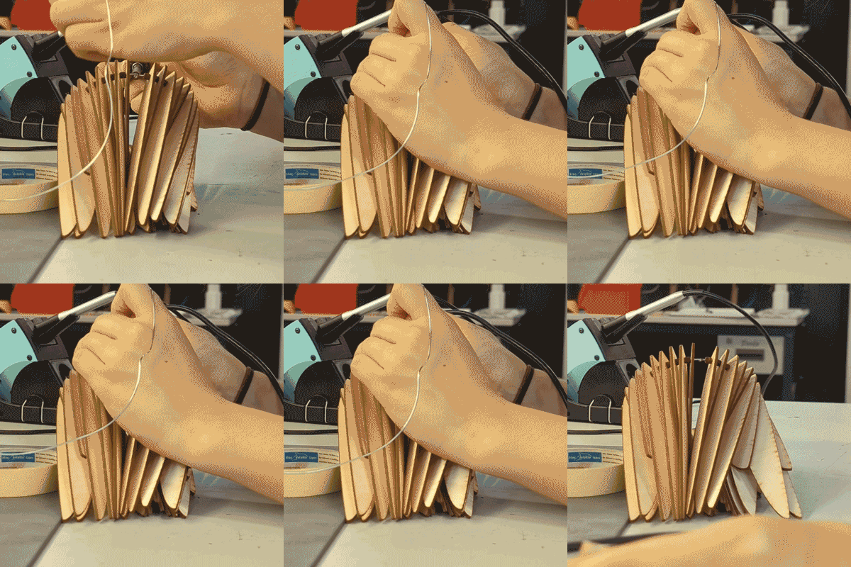
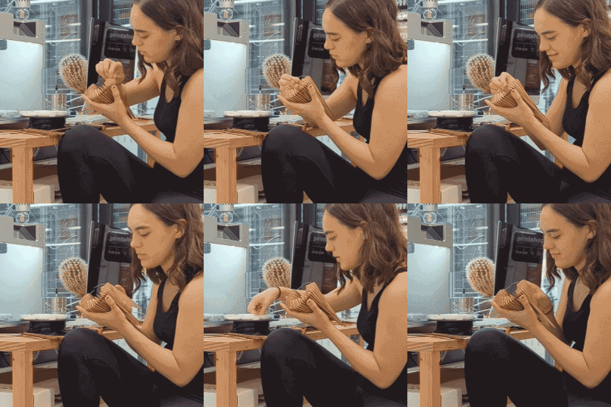
Soldering a ring
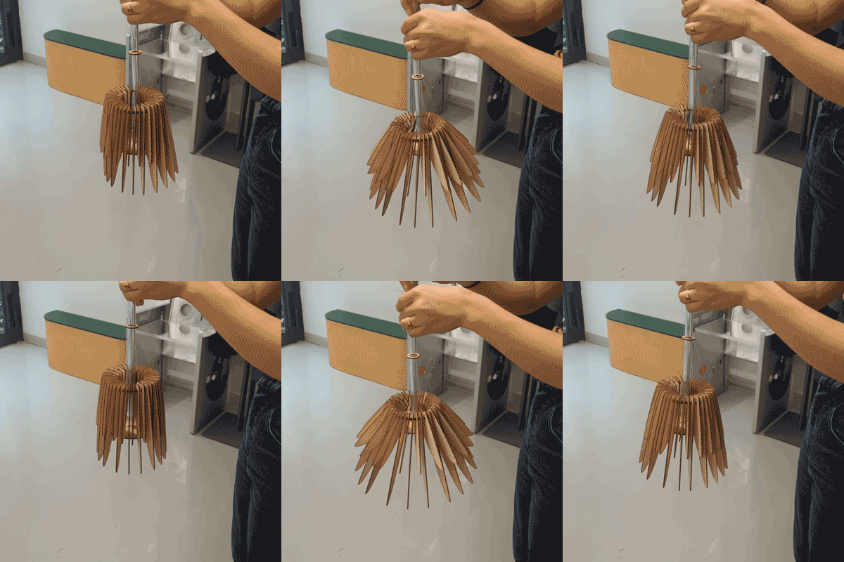
Testing the thread guide and bottom platform
PROTOTYPING — ROUND 2
I then made a prototype at approximately a 1:2 scale of the final dimensions I wanted. This prototype was going to be functional, so I quickly made some leaps in additional parts: spacers to keep the "fins" of the lamp from colliding, a thread guide to organize the pulling strings, and a bottom platform to provide the contact to spread the fins.
I then attached a pulley to a simple stepper motor and added an LDR to the circuit. I wrote my first version of the code, initiating it with a phone flashlight to simulate a lightbulb turning on, and utilizing the stepper's count to determine the height of the ring and fins.
First successful test! (0:07)
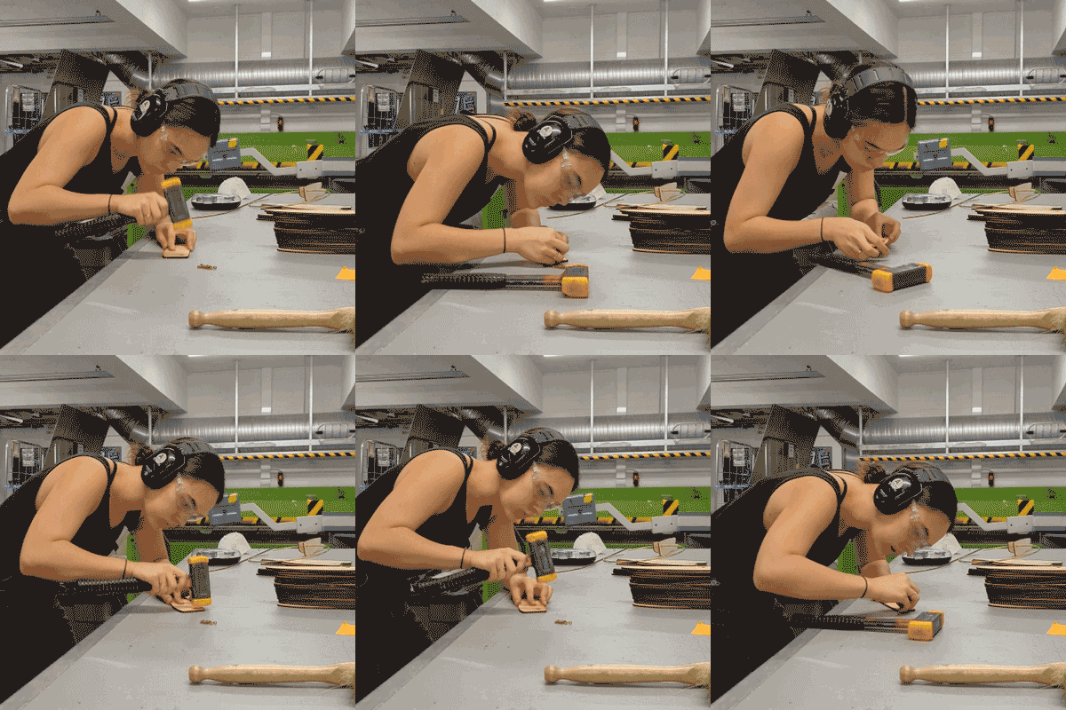
Hammering brass rings into the joint to prevent wear
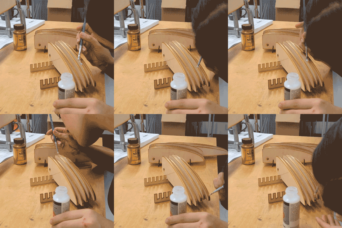
Painting & varnishing the undersides of the fins
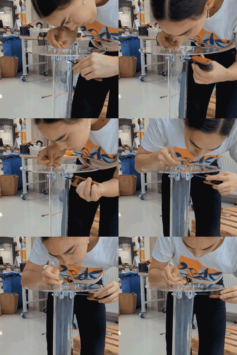
Switching to an acrylic platform and tube
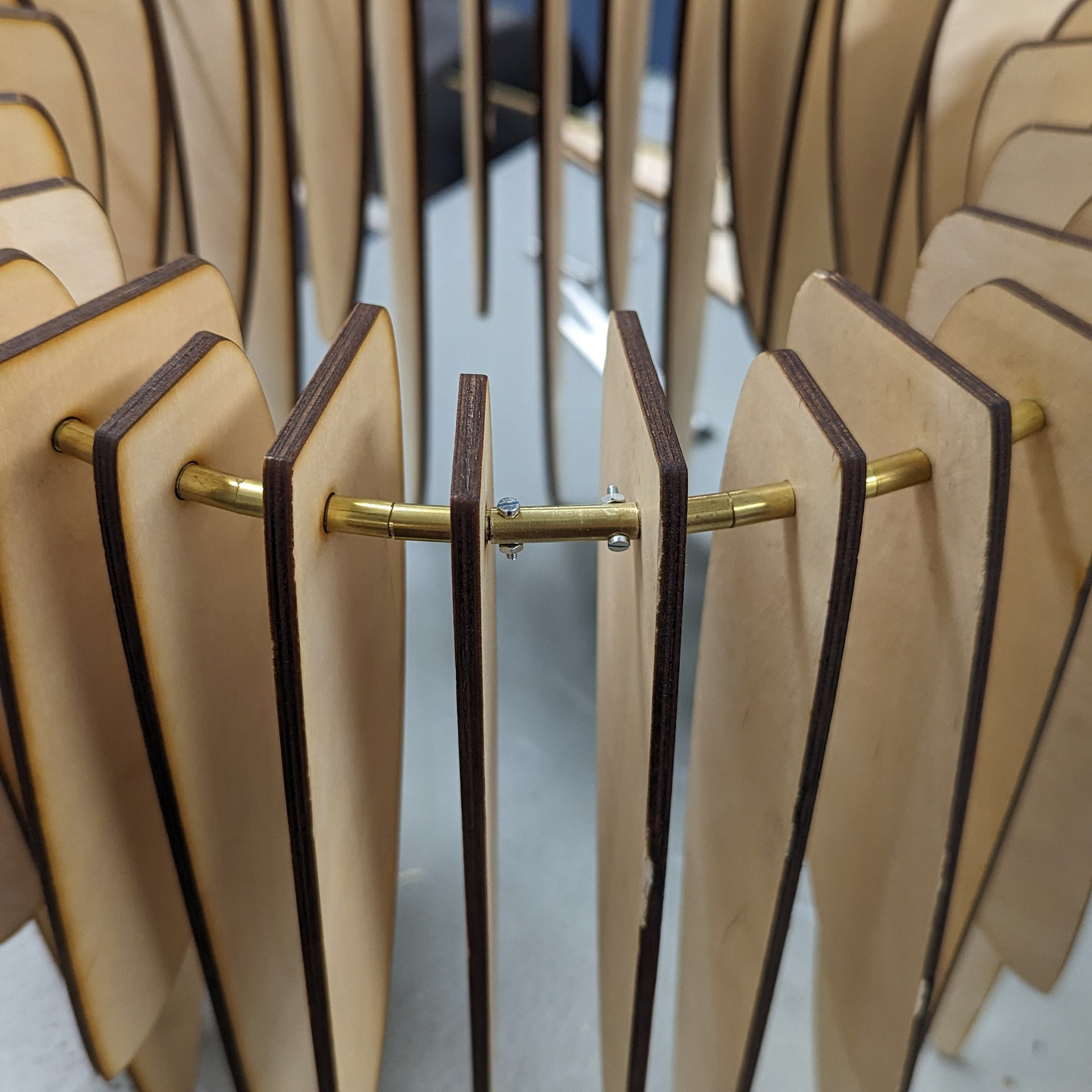
New brass ring with brass spacers
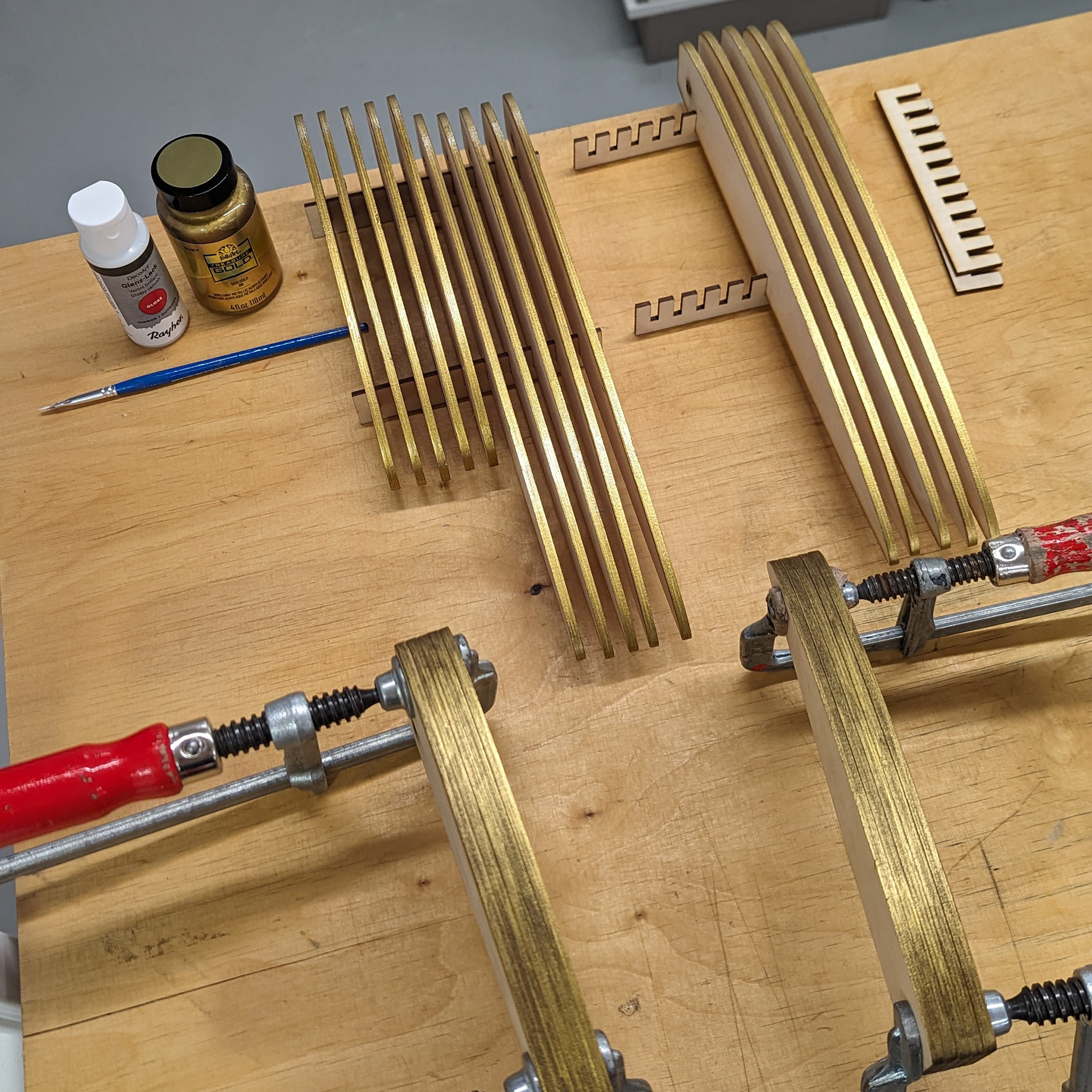
New gold paint on the undersides of the fins
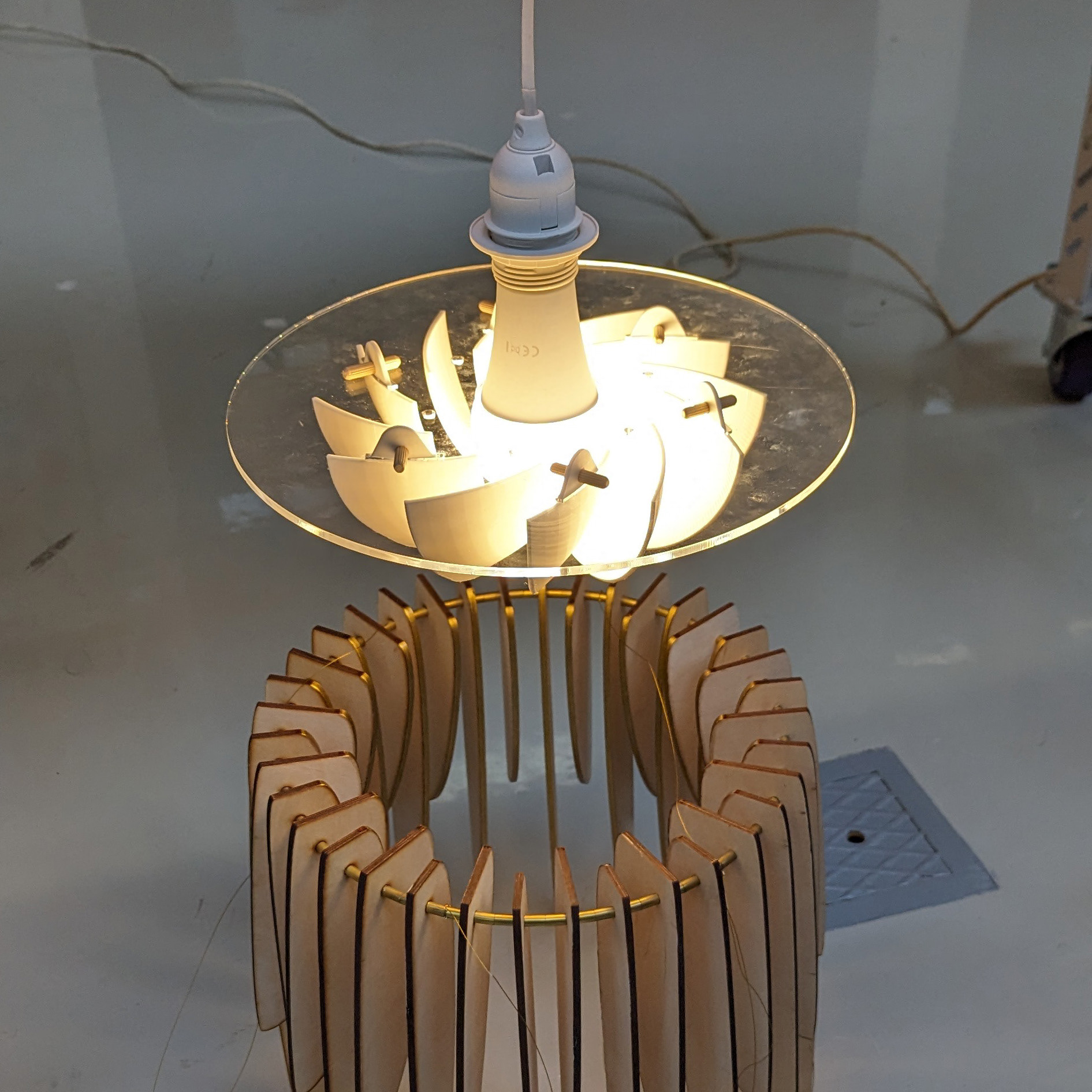
New 3D-printed lampshade, connected with dowels
PROTOTYPING — ROUND 3
As I sized up to the final form, the number of modifications significantly increased. Most of the design changes were related to the longevity and lighting design of the piece.
The first major modification was switching the material of the fins from birch plywood to balsa wood; the significantly lighter wood put less strain on the electronics and mechanics. Additionally, to protect the softer balsa wood from wear, I hammered brass rings into the inside of the hole that connects the fins to the central ring. The undersides of the fins were painted gold and varnished for durability, as well as an added warmth and glow.
The central tube and bottom platform were changed from wood to acrylic so as to let more light through. This of course added more weight, so sturdy brackets were installed to keep the platform and tube together after the impact from the fins dropping. Instead of having a bare lightbulb, one of my colleagues recommended using an old design from a research group at the university—the spiraling, white, 3D-printed lampshade was designed to perfectly diffuse light. I modified the design to fit with dowels onto the bottom platform.
Altogether, many of the design changes I made were with the intention of easy disassembly—I didn't want to glue the lampshade to the acrylic in case parts broke one day, so the dowels made for a perfect reversible attachment.
Finally, for the programming and electronics, I stopped relying on stepper counts to determine the height of the lamp and implemented an ultrasonic sensor at the top of the tube. The ultrasonic would read the distance of the ring from the top, and therefore help to zero out the stepper when it inevitably drifted with gravity.
The lamp self-correcting its height based on readings from the ultrasonic sensor (0:07)
SPECIAL THANKS
Anna Kuukka
Erwin Laiho
Sushant Passi
Jasmine Xie
